- 您現在的位置:買賣IC網 > PDF目錄299877 > S1C60L09D 4-BIT, MROM, 0.08 MHz, MICROCONTROLLER, UUC70 PDF資料下載
參數資料
| 型號: | S1C60L09D |
| 元件分類: | 微控制器/微處理器 |
| 英文描述: | 4-BIT, MROM, 0.08 MHz, MICROCONTROLLER, UUC70 |
| 封裝: | DIE-70 |
| 文件頁數: | 28/62頁 |
| 文件大小: | 476K |
| 代理商: | S1C60L09D |
第1頁第2頁第3頁第4頁第5頁第6頁第7頁第8頁第9頁第10頁第11頁第12頁第13頁第14頁第15頁第16頁第17頁第18頁第19頁第20頁第21頁第22頁第23頁第24頁第25頁第26頁第27頁當前第28頁第29頁第30頁第31頁第32頁第33頁第34頁第35頁第36頁第37頁第38頁第39頁第40頁第41頁第42頁第43頁第44頁第45頁第46頁第47頁第48頁第49頁第50頁第51頁第52頁第53頁第54頁第55頁第56頁第57頁第58頁第59頁第60頁第61頁第62頁
CHAPTER 4: PERIPHERAL CIRCUITS AND OPERATION (LCD Driver)
28
EPSON
S1C60N09 TECHNICAL MANUAL
4.6.3 Mask option
(1) Segment allocation
As shown in Figure 4.l.1, display data is decided by the data written to the display memory at address
40H–6FH or C0H–EFH.
The mask option enables the display memory to be allocated entirely to either 40H–6FH (R/W) or
C0H–EFH (W only).
The address and bits of the display memory can be made to correspond to the segment terminals
(SEG0–SEG37) in any combination through mask option. This simplifies design by increasing the
degree of freedom with which the liquid crystal panel can be designed.
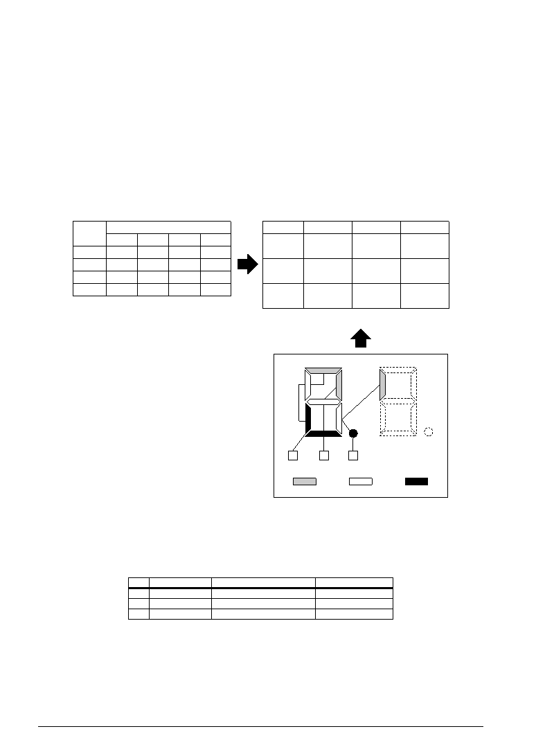
Figure 4.6.3.1 shows an example of the relationship between the LCD segments (on the panel) and the
display memory (when 40H–6FH is selected) in the case of 1/3 duty.
aa'
f
f'
g'
g
ee'
d
d'
p'
p
c'
b'
b
c
SEG10
SEG11
SEG12
Common 0
Common 1
Common 2
06AH
06BH
06CH
06DH
Address
d
p
d'
p'
D3
c
g
c'
g'
D2
b
f
b'
f'
D1
a
e
a'
e'
D0
Data
Display data memory allocation
SEG10
SEG11
SEG12
6A, D0
(a)
6A, D1
(b)
6D, D1
(f')
6B, D1
(f)
6B, D2
(g)
6A, D2
(c)
6B, D0
(e)
6A, D3
(d)
6B, D3
(p)
Pin address allocation
Common 0
Common 1
Common 2
Fig. 4.6.3.1 Segment allocation
(2) Drive duty
According to the mask option, either 1/4, 1/3 or 1/2 duty can be selected as the LCD drive duty.
Table 4.6.3.1 shows the differences in the number of segments according to the selected duty.
Table 4.6.3.1 Differences according to selected duty
Duty
1/4
1/3
1/2
COM used
COM0–COM3
COM0–COM2
COM0–COM1
Max. number of segments
152 (38
× 4)
114 (38
× 3)
76 (38
× 2)
Frame frequency *
fOSC/1,024 (32 Hz)
f/768 (42.7 Hz)
fOSC/1,024 (32 Hz)
When fOSC = 32 kHz
相關PDF資料 |
PDF描述 |
|---|---|
| S1C63358F | 4-BIT, MROM, 4.1 MHz, MICROCONTROLLER, PQFP100 |
| S1D13503F00A | 1024 X 768 PIXELS CRT OR FLAT PNL GRPH DSPL CTLR, PQFP100 |
| S1DGPC | SLIDE SWITCH, SPDT, LATCHED, 0.05A, 48VDC, THROUGH HOLE-STRAIGHT |
| S1F | 1.2 A, 50 V, SCR, TO-92 |
| S2A | 1.5 A, 100 V, SCR, TO-92 |
相關代理商/技術參數 |
參數描述 |
|---|---|
| S1C60L16 | 制造商:EPSON 制造商全稱:EPSON 功能描述:4-bit Single Chip Microcomputer |
| S1C60N05 | 制造商:EPSON 制造商全稱:EPSON 功能描述:4-bit Single Chip Microcomputer |
| S1C60N08 | 制造商:EPSON 制造商全稱:EPSON 功能描述:4-bit Single Chip Microcomputer |
| S1C60N16 | 制造商:EPSON 制造商全稱:EPSON 功能描述:4-bit Single Chip Microcomputer |
| S1C60R08 | 制造商:EPSON 制造商全稱:EPSON 功能描述:4-bit Single Chip Microcomputer |
發布緊急采購,3分鐘左右您將得到回復。