- 您現在的位置:買賣IC網 > PDF目錄3809 > PIC32MX675F512L-80I/PF (Microchip Technology)IC MCU 32BIT 512KB FLASH 100TQFP PDF資料下載
參數資料
| 型號: | PIC32MX675F512L-80I/PF |
| 廠商: | Microchip Technology |
| 文件頁數: | 23/64頁 |
| 文件大小: | 0K |
| 描述: | IC MCU 32BIT 512KB FLASH 100TQFP |
| 特色產品: | 32-Bit PIC? Microcontroller PIC32 32-Bit MCU Families |
| 標準包裝: | 90 |
| 系列: | PIC® 32MX |
| 核心處理器: | MIPS32? M4K? |
| 芯體尺寸: | 32-位 |
| 速度: | 80MHz |
| 連通性: | 以太網,I²C,SPI,UART/USART,USB OTG |
| 外圍設備: | 欠壓檢測/復位,DMA,POR,PWM,WDT |
| 輸入/輸出數: | 85 |
| 程序存儲器容量: | 512KB(512K x 8) |
| 程序存儲器類型: | 閃存 |
| RAM 容量: | 64K x 8 |
| 電壓 - 電源 (Vcc/Vdd): | 2.3 V ~ 3.6 V |
| 數據轉換器: | A/D 16x10b |
| 振蕩器型: | 內部 |
| 工作溫度: | -40°C ~ 85°C |
| 封裝/外殼: | 100-TQFP |
| 包裝: | 托盤 |
| 產品目錄頁面: | 650 (CN2011-ZH PDF) |
第1頁第2頁第3頁第4頁第5頁第6頁第7頁第8頁第9頁第10頁第11頁第12頁第13頁第14頁第15頁第16頁第17頁第18頁第19頁第20頁第21頁第22頁當前第23頁第24頁第25頁第26頁第27頁第28頁第29頁第30頁第31頁第32頁第33頁第34頁第35頁第36頁第37頁第38頁第39頁第40頁第41頁第42頁第43頁第44頁第45頁第46頁第47頁第48頁第49頁第50頁第51頁第52頁第53頁第54頁第55頁第56頁第57頁第58頁第59頁第60頁第61頁第62頁第63頁第64頁
2007-2012 Microchip Technology Inc.
DS61145K-page 3
PIC32MX
3.0
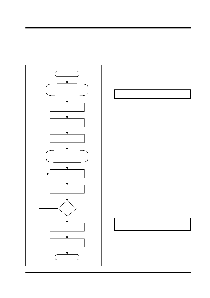
PROGRAMMING STEPS
All tool programmers must perform a common set of
steps, regardless of the actual method being used.
Figure 3-1 shows the set of steps to program PIC32MX
devices.
FIGURE 3-1:
PROGRAMMING FLOW
The following sequence lists the steps, with a brief
explanation of each step. More detailed information
about the steps is available in the following sections.
1.
Connect to the Target Device.
To ensure successful programming, all required
pins must be connected to appropriate signals.
in this document for more information.
2.
Place the Target Device in Programming Mode.
For 2-wire programming methods, the target
device must be placed in a special programming
mode (Enhanced ICSP) before executing any
other steps.
ICSP Mode” for more information.
3.
Check the Status of the Device.
Step 3 checks the status of the device to ensure
it is ready to receive information from the
programmer.
more information.
4.
Erase the Target Device.
If the target memory block in the device is not
blank, or if the device is code-protected, an
erase
step
must
be
performed
before
programming any new data.
See Section 9.0 “Erasing the Device” for
more information.
5.
Enter Programming Mode.
Step 5 verifies that the device is not code-
protected and boots the TAP controller to start
sending and receiving data to and from the
PIC32MX CPU.
Mode” for more information.
6.
Download the Programming Executive (PE).
The PE is a small block of executable code that
is downloaded into the RAM of the target device.
It will receive and program the actual data.
See
for
more
information.
Done
Exit Programming Mode
Verify Device
Done
Initiate Flash Write
Download a Data Block
Download the PE
(Optional)
Enter Serial Exec Mode
Erase Device
Check Device Status
Start
Enter Enhanced ICSP
(Only required for 2-wire)
No
Yes
Note:
For the 4-wire programming methods,
Step 2 is not required.
Note:
If the programming method being used
does not require the PE, Step 6 is not
required.
發布緊急采購,3分鐘左右您將得到回復。