- 您現在的位置:買賣IC網 > PDF目錄373962 > AD9289BBC-65EB (Analog Devices, Inc.) Quad 8-Bit, 65 MSPS Serial LVDS 3V A/D Converter PDF資料下載
參數資料
| 型號: | AD9289BBC-65EB |
| 廠商: | Analog Devices, Inc. |
| 英文描述: | Quad 8-Bit, 65 MSPS Serial LVDS 3V A/D Converter |
| 中文描述: | 四8位,65 MSPS的串行LVDS 3V的A / D轉換 |
| 文件頁數: | 10/16頁 |
| 文件大小: | 1376K |
| 代理商: | AD9289BBC-65EB |
AD9289 Prelimnary Technical Data
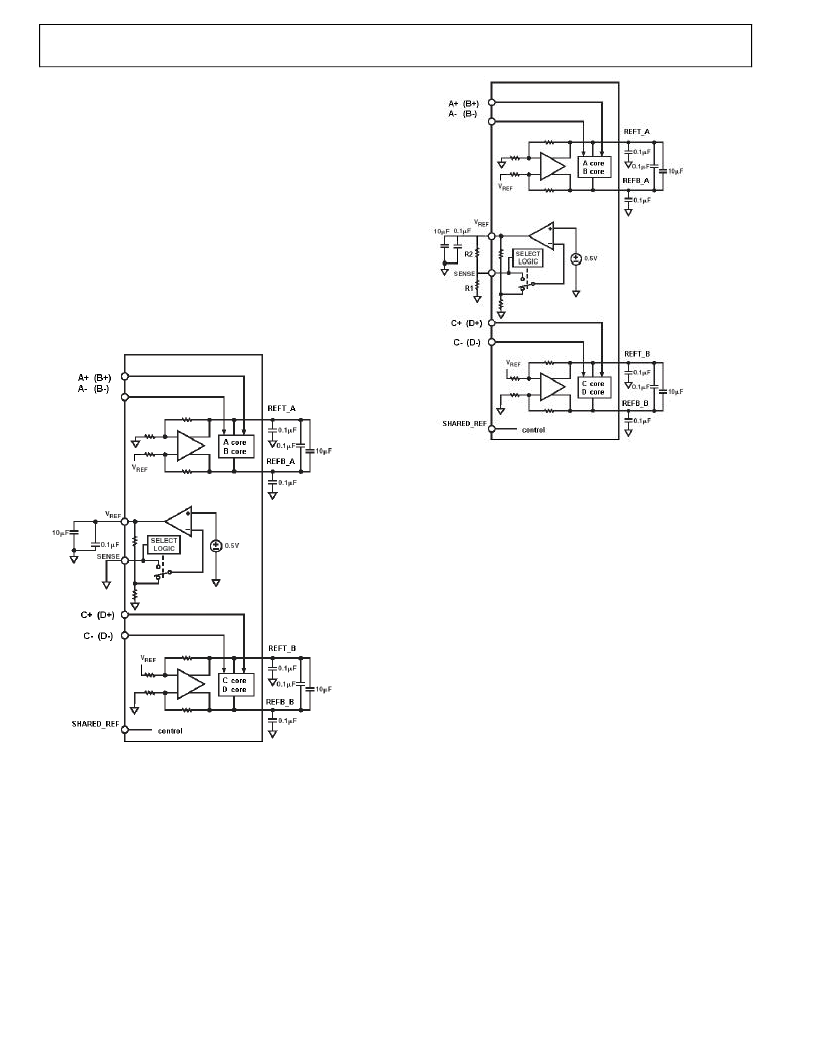
Internal Reference Connection
A comparator within the AD9289 detects the potential at the
SENSE pin and configures the reference into four possible states,
which are summarized in Table I. If SENSE is grounded, the
reference amplifier switch is connected to the internal resistor
divider (see Figure 2), setting VREF to 1 V. Connecting the
SENSE pin to VREF switches the reference amplifier output to the
SENSE pin, completing the loop and providing a 0.5 V reference
output. If a resistor divider is connected as shown in Figure 3, the
switch will
again be set to the SENSE pin. This will put the reference
amplifier in a non-inverting mode with the VREF output defined as
follows:
VREF = .5 * (1 +R2/R1)
In all reference configurations, REFT and REFB drive the ADC
core and establish its input span. The input range of the ADC
always equals twice the voltage at the reference pin for either an
internal or an external reference.
Rev. PrJ | Page 10 of 16
6/25/2004
Figure 4.
Internal Reference Connection
Figure 5.
Programmable Reference Connection
External Reference Operation
The use of an external reference may be necessary to enhance the
gain accuracy of the ADC or improve thermal drift characteristics.
When multiple ADCs track one another, a single reference
(internal or external) may be necessary to reduce gain matching
errors to an acceptable level. A high precision external reference
may also be selected to provide lower gain and offset temperature
drift. External reference mode is chosen by tying SENSE pin to
AVDD and driving VREF with external reference.
相關PDF資料 |
PDF描述 |
|---|---|
| AD9300 | 4 x 1 Wideband Video Multiplexer |
| AD9300KP | 4 x 1 Wideband Video Multiplexer |
| AD9300KQ | 4 x 1 Wideband Video Multiplexer |
| AD9410 | 10-Bit, 210 MSPS A/D Converter |
| AD9410BSQ | 10-Bit, 210 MSPS A/D Converter |
相關代理商/技術參數 |
參數描述 |
|---|---|
| AD9289BBCZ | 制造商:Analog Devices 功能描述:ADC Quad Pipelined 65Msps 8-bit Serial 64-Pin CSP-BGA |
| AD9300 | 制造商:AD 制造商全稱:Analog Devices 功能描述:4 x 1 Wideband Video Multiplexer |
| AD9300KP | 制造商:Analog Devices 功能描述: 制造商:Analog Devices 功能描述:4-CHANNEL, VIDEO MULTIPLEXER, PQCC20 |
| AD9300KP-REEL | 制造商:Analog Devices 功能描述: |
| AD9300KQ | 制造商:AD 制造商全稱:Analog Devices 功能描述:4 x 1 Wideband Video Multiplexer |
發布緊急采購,3分鐘左右您將得到回復。